Friday, March 14, 2014

Stepper Motor Interface PIC18F4550 Microcontroller

Stepper Motor Driver using PIC18F4550

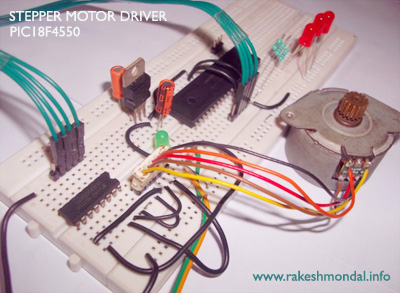
This is a simple project for running a unipolar Stepper Motor using a PIC18F microcontroller. The Microcontroller is coded to run the stepper motor in three different stepping modes. The Stepper motor is interfaced with pic18f4550 using a ULN2003 chip. The Stepper motor is running in 9 volts, But pic18f4550 cannot draw 9 volts hence a uln2003 is used. 

Stepper motor Interface to PIC18F4550


The Microcontroller cycles three modes of stepper motor stepping such as Single, Half wave stepping and Full wave stepping with a delay of 2-3 seconds of delay in between. The Stepper motor Drive is coded with mplab x ide and XC8 Compiler.



Stepper Motor Source code

The Stepper Motor coils are connected to PIC18F4550 pins, RD4, RD5, RD6 and RD7, and then these pins are interfaced with ULN2003.

Stepper Motor Schematic PIC18F4550

According two the two source code posted here, two schematic is posted. The power source is common for both ULN2003 and pic18F4550 hence an IC 7805 to maintain input constant at 5 V.

Stepper Motor Project

Download and install mplab x ide along with XC8 Compiler (Either windows and Linux) and then download the project from the link below.
Run the project and burn the firmware into the microcontroller using your favorable microcontroller programmer such as JDM programmer or PICKIT2 programmer.


Testing the Stepper Motor
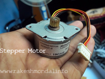
This is a basic mechanism to test weather the stepper Motor is working. It is a basic test to see if each of the pins are working. The Motor used here is an old unipolar Stepper motor.


Testing the Stepper Pulse 

After burning the stepper motor with the source code, Before interfacing the Microcontroller to the PIC18F4550, to test - few LED’s are connected across the Microcontroller pins, just to make sure if the pulses are getting generated the way as it is supposed to be for the stepper motor. After successful testing the Stepper Motor will be interfaced with the microcontroller via ULN2003.
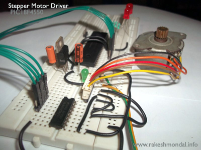
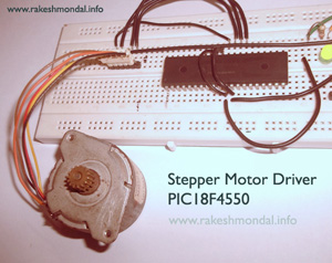


After successfully testing the stepper motor pulse generated by the microcontroller , connect the stepper Motor across the microcontroller through the uln2003 IC.

Please refer my next tutorial for running a stepper motor using a computer via USB communication.

Thanks for Watching


Related post

USB STEPPER MOTOR DRIVER
Collection of Stepper Motor Tutorials and Projects


Tuesday, March 11, 2014

LOW RPM High Torque DC Motor Interface to PIC18F4550 | Robotics

This video is a demonstration of a LOW RPM High Torque DC motor interfaced with a PIC18F4550 microcontroller through a L293D Motor Driver circuit for a small tutorial robot. The pulses generated on the microcontroller pins are interfaced to the L293D which is guiding the Motor to run in Clockwise, Anti clockwise or Halt.

The low rpm and high torque of this dc motor makes it perfect for robotic applications. To increase the torque at the wheels, sometimes additional gears are necessary, but this specific high torque dc motor comes with an in built gear mechanism, providing necessary torque. This video shows a demonstration of the DC motors working before the entire circuitry was installed on a 4 wheel differential drive robot


The motor is operating on 12 Volts which is managed by the L293D, however the power to the microcontroller is being provided by same power source with a IC 7805 voltage regulator to keep input voltage to microcontroller strictly at 5 Volts.


The microcontroller is coded with Mplab X IDE and XC8 Compiler.

Thanks for watching

Ron

Monday, November 11, 2013

MPLAB X IDE Ubuntu Linux


Ref- Mplab X IDE Tutorial 

The only pain that I had with “Mplab” was that the interface was too old and unfortunately, Linux versions of Mplab were not available. So, to program my PIC18F4550 microcontroller I had to install a Virtual machine on my Linux (Ubuntu) and run windows on it. So, I had to be dependent on windows Virtual machine to use MPLAB IDE.

MPLAB X IDE and XC8 Compiler on Linux Ubuntu with advanced features
However the Mplab new version, that is Mplab X IDE solved that problem big time. Hurray it can be now installed on Linux machine too. Yes, the new versions still has some old bugs carried over with old Mplab IDE to its new makeover, but still at least it saved a lot of trouble by eliminating dependency on Windows computer totally. I am not a great fan of windows since I migrated to Linux 3 years ago.


Yes, the new MPLAB X IDE does look more like a cracked version of NetBeans but I guess I am OK with that. Now it looks better and has all the good features. I have been working on NetBeans long ago for my java projects so sometimes working on Mplab X IDE feels more like a tweaked version of NetBeans to me, but that absolutely fine.

Starting Mplab X IDE in Linux Ubuntu


In old versions, I had to install different compiler for programming a pic16f and a pic18f  but with new XC8 compiler took care of all those issues, as it doesn't require having different compiler suits. The XC8 C compiler alone handles most of them together.

Installing on Mplab X on Ubuntu was little tricky, But it all worked out favorably well. The java had to be updated before I could begin installing the Mplab X IDE on Linux I had to change the file permission. On Ubuntu before we can execute installation files it requires to make the file Executable by enabling “Allow Executing the Program as File” from properties and it started the installation like a charm without any trouble.


Linux Terminal and java update for Mplab X IDE and XC8 C

Mplab X IDE and XC8 C compiler on Linux Operating system

Mplab X IDE and XC8 C Installation


The User interface looks better, and I found some exiting things about Mplab X IDE. The execution happens faster and in the older version if you miss a semicolon then you had to wait till you compile the code and a window will tell you that you missed something,
But in the interactive version that problem also got solved, as it provides auto suggestions and point out right there if you are missing something or if you have made a typo in the source code, just like any other latest IDEs.


MPLAB X IDE starting after Installation - Loading Modules


Another thing which I noticed was the size of the .hex files after compiling. Soon after installation of Mplab X ide and XC8 Compiler, for the sake of testing I wrote a small code to blink led on pic18f4550, with first line of code as #include<p18f4550.h>. In XC8 compiler instead of include<p18f4550> you can also write Include<PIC18f4550> , I guess they have made some changes with libraries so it supports old and new libraries.


After compiling the Source code for the first time in new MPLAB X , I was little puzzled to see the output hex file appeared far short to me. For some time I actually though that there might be some issue with the IDE or I missed out something in the coding.

Mplab X IDE Tutorial  Programming and coding


So I checked my coding again and recompiled, but still there was no difference. To test out , I burned the new hex file into the microcontroller and I was shocked that it was working the way it was supposed to work. The led’s were blinking.

Conclusion was quiet clear that the output generated by Mplab X IDE was optimized and much shorter then what the old version of IDE did. I compiled the same code again with an old version of MPLAB and it generated a much more lengthy output then that of Mplab X.


You can find a short tutorial and case study on my website- MPLAB X post with some example coding as demonstration. Please visit my post for a bit more details and the whole comparison of output hex generated by Mplab X IDE and the old Mplab.


>>>>>>>>>> MPLAB X IDE Tutorial


MPLAB X IDE http://www.rakeshmondal.info/Mplab-X-IDE-XC8-Tutorial-Blinking-LED


Tuesday, March 20, 2012

A simple robot under construction "Robin v1.0"

A Simple Robot Tutorial


(On request by some friends).

I am making this robot completely on request, for the purpose of making Simple tutorial for making your own robot just for beginners (Note: not an expert level one, just a simple one for beginners , anyone can make it in simple steps . And coding is also not complex.) It will be based on simple AGENT PROGRAM (A.I)

Once I am done with this robot, i will upload a complete tutorial for making this robot on my website and blogs.I found a small broken toy car which had perfect tires , so decided to break it and decoded to transform it into a small robot.


This robot has no sensors , I call it as “robin v1.0” , in next robot I will add an IR [Infra red ]sensors and make it as an object detection and it will be “robin v1.1” , for now lets begin with our “robin v1.0”


I will use simple D.C motor and pic18f4550 microcontroller. Pic18f4550 is one of my favorite microcontroller because of its USB features. [to be very frank u can use 555 timer too to make my robin v1.0 , but since you cannot code a 555 and microcontrollers gives more degree of freedom to code, so I will go with microcontroller , plus u can code it the way u want it.] In My next version would be Robin v1.1, v1.2 where i will use Sensors and some complex motors like . Stepper motor and Servos. {PWM}


More details coming Soon

Keep reading, Thanks


Rakesh Ron


Please Visit my Website for more projects

www.rakeshmondal.info


My channel for more

http://www.youtube.com/user/ronymandal123/featured

http://www.facebook.com/microcontrollerinfo


www.rakeshmondal.info


Friday, January 20, 2012

JHD 16 2a LCD working with pic18f4550 "PICDEM FS USB"

JHD 16 2a LCD working with pic18f4550 "PICDEM FS USB"


Its a small demonstration of a jhd 16 2a lcd, jhd 16 2a is a small 2x16 character lcd , that i am controlling with PIC18F4550 microcontroller .


jhd 162A lcd interfacing‎ 2x16 char , 16 pins


The board is a home made PICDEM FS USB development board that i have made, the jhd 16 2a is connected to the microcontroller , i have used small C# application that i have made with a open-source LCD framework found over Internet. The Application is written C# that is controlling the text.


I will be posting /posted a detailed tutorial on my page and on instructables.


http://www.facebook.com/microcontrollerinfo


Thanks for watching.


Rakesh Ron


www.rakeshmondal.info

Monday, January 2, 2012

ROBOT wheels. Sensing Position with a mouse wheel.

ROBOT WHEELS


Using mouse wheels, LCD display , pic18f2550 , C# , and MPLAB IDE (HI-TECH C compiler for 18f )


The Project is based on pic18f2550 interfaced with a 2x16 LCD [JHD 162A] and a mouse. I found an unused mouse and decided to use it in my robot.


You can Interface this project with your robot , and have it all displayed as a cool display on the LCD.


This project uses Visual 2010 C# , and is interfaced with pic18f2550


BASE FIRMWARE written in MPLAB IDE and HI-tech C compiler
and for mouse i am using a small software written in c#
in C# i am using mouse wheel event e delta property.

C# CONCEPT
=========

 Create a Mouse wheel event
{
      IF (e.Delta >0)
Display ("forward")
else
Display ("Backwards:)
}

Looks simple right?

:) :)


Thanks for watching

IF you wish to download the Edelta property Mouse wheel event project then you can get it on the link below.

E.delta property Mouse wheel


AND HAPPY XMAS  BY THE WAY :) [IT WAS ACTUALLY DONE ON 25TH DEC ]


Thanks for watching
Ron
www.rakeshmondal.info


Monday, November 28, 2011

USB DC Motor Driver using PIC18f4550


Hey friends its ron here,

This a small project on controlling D.C motor with USB pic18f4550 interface board with L293D motor controller.

To read the basics of Motor Driver Follow my Motor Driver Link

A small application is controlling my pic18f4550 USB interface board with my computer, enabling me to control my board with keyboard. The output the microcontroller is given to the input of a l293d motor controller , hence enabling me to control my DC motor in ( forward / reverse ) that is Clockwise and Counter Clockwise | anti-clock (cw/ccw) direction. For more info please watch my previous post on L293d motor controller. It must give you some idea if you a complete beginner.

Please watch both the video below for its demonstration.


SHOT VIDEO


FULL DESCRIPTION 


NOTE:  If you wish to make this USB pic18f4550 microcontroller board then follow my project on my website for Schematics, Firmware and Codes.
USB INTERFACE DEVELOPMENT BOARD USING PIC18F4550


Thanks for reading

Rakesh Ron.

ron

www.rakeshmondal.info

L293D IC DC Motor Driver Chip Introduction

INTRODUCTION TO L293D DC MOTOR Driver

If you really interested in robotics and controlling (electronics) stuffs then one of the most basic thing is to control devices like DC Motors, Stepper Motors , Servo (with pwm) etc. which one of the important topic in robotics.

Today I am going to show you some basics of L293D DC motor controller, Its a integrated circuit that enables you to control motor rotation ( forward / reverse ) that is Clockwise and Counter Clockwise | anti-clock (cw / ccw). I will provide the basics in this post and in my next posts I will show you working and application of this L293D motor Driver interface with a microcontroller ( PIC18F4550 microcontroller )


You can find the pin diagram of l293d motor drive with a short Google, the chip is kind of self explanatory when you see the pin diagram. With one single chip you can drive two DC motors to rotate in forward/ reverse direction on your command.

This chip understands only logic 0 and logic 1 signals as input control signal , we are going to generate the logic 0 and 1 with the help of a pic18f4550 microcontroller, (in my next post), the logic 0 and 1 will be fed to the input of the l293d and motor will be connected to the out pins of l293d.


There are two inputs and two outputs on either sides of the chip, both sides of the chip can control one motor each. so a single chip can operate two DC motors.


Each operational unit has to be activated or enabled before you can use it. So connect the pin1 (chip enable) to VCC if you wish to use to activate one side, and so as another "chip enable" pin in you want to use second operational unit.

NOTE: Connect all GND to common ground , and DO NOT FORGET to connect the GND of microcontroller with l293d GND.

In my next post I will show its demonstration with a pic18f4550 USB interface board , computer USB and keyboard controlled DC motor with L293D.


Thanks for reading

Rakesh Ron

ron


NOTE:  If you wish to make this USB pic18f4550 microcontroller board then follow my project on my website for Schematics, Firmware and Codes.
USB DEMO INTERFACE DEVELOPMENT BOARD USING PIC18F4550


A personal request plz join my community on facebook for more similar stuffs :D

http://www.facebook.com/microcontrollerinfo


Tuesday, June 14, 2011

BOOTLOADING PIC18F4550 USB Demo Interface Board


BOOTLOAD THE PIC18F4550 – FIRMWARE UPDATING

SETTING THE PIC18F4550 IN RD/WR ( BOOTLOAD ) MODE FOR BOOTLOADING


Rakesh Mondal 


Ron
www.rakeshmondal.info

USB Demo Interface Development Board (PIC18F4550)

USB INTERFACE DEVELOPMENT BOARD 
  

This is a USB Interface development board that I have made based on www.microchip.com forums , I made board to find a way to control my stepper motor or my relays and DC from computer laptop.
So I had to finally use microcontroller as SERIAL PORTS are not available in Laptops.
And as there are no LPT in laptops so USB to serial converters cables don't work.


Please follow my website for more.
How to make a USB Interface board using PIC18F4550 Microcontroller 


Rakesh Mondal 
RON
www.rakeshmondal.info

Robot based on USB (PIC18F4550)

Robot based on USB (PIC18F4550)


Hey friends , sorry for being late , I was very much busy in my works and I was really finding it hard to manage time for blogging as I had my exams and I was working on some websites .

Here is my latest work,

Its a robot based On USB Interface , I have not used any stepper motor in it , but some high torque LOW RPM motors did job for me perfectly.


The robot is controlled with pic18f4550 microcontroller, the pins are interfaced with uln2003 and then finally to l293d (hbridge).To generate more controls i used some logic gates like AND and NOT gate .The firmware is programmed in MPlab.
The 360 degree camera view is provided with a kinda robot arm mounted with camera , which can provide view in both x and y plane.
The other features are motion detector,IR object detection, laser ranger , and also included a small blue ray laser to bust small things like balloon, tapes etc etc etc etc etc. its connected and controlled with USB, for the moment is wired but it can become completely wireless by adding just an extra wireless hub .
All controlls are generated with .net c# (visual 2010).


OTHER LINKS


http://letsmakerobots.com/node/26168

http://www.instructables.com/id/USB-ROBOT-BASED-ON-PIC18F4550-DEMO-BOARD/

I am currently working very hard to prepare a detailed tutorial on this robot.
I will be posting then soon to my website


THANKS FOR READING


Thanks for Reading
Rakesh Mondal Ron


Related Articles

USB Stepper Motor Driver
Stepper Motor Driver Using PIC18F4550
Stepper Motor Driver Tutorials
USB Interface Board

For more and Questions Please Visit My personal Website
www.rakeshmondal.info


Saturday, November 20, 2010

CD / DVD DRIVE STEPPER MOTOR WIRE LABELING

CD /DVD DRIVE STEPPER MOTOR LABELING

Recently I have been experimenting with many DVD drive stepper motors and I found it to be same as that one if floppy drive labeling. The stepper motor in DVD/CD drive are exactly same as that of the floppy drive. The only difference is that they are not hybrid stepper motor. The stepper motor in the DVD drive are standard 4- wire stepper motor.
The labeling for the wires are exactly same as that one I mentioned in my previous post here.
Get some old DVD drive from vendor and after dismantling it you can get a good lens that can be used for some laser game gun melting some balloon, a DC motor and 2 stepper motor .One small stepper motor for panning of the drive tray and one for running the disk.

Both stepper motor inside the DVD are 4 –wire stepper. Labeling same as FDD, one comm and rest as U ,V , W.

Thank you.
Keep reading.


HOW TO USE A FLOPPY DRIVE STEPPER MOTOR FOR PROJECTS


IDENTIFY THE WIRES OF A FLOPPY DRIVE STEPPER MOTOR

Author: Rakesh Mondal
Domain: Understanding the labeling of the wires of a floppy drive stepper motor.
STEPPER MOTOR IN A FLOPPY DRIVE

It is possible to use the stepper motors from Floppy drives and CD/DVD Drive from unused left out Drives.
Generally stepper motor are costly, in India the stepper may cost around 250 to 500 rupees, to reduce the cost you can use a stepper motor from a floppy drive.
The stepper motor used for running the disk in the fdd are generally hybrid stepper motor ,in case you want to know what is stepper motor can you can read in Wikipedia, it has detailed description.
Here I will teach you how to use a stepper motor from fdd and identify the motor wires without a multi meter.
As a part of my robotic project I was searching on net about the identification of the stepper motor wires but I didn't find any relevant tutorial, so I had to go through some research work to make it possible.

After 2 days of hit and trial I came out with an understanding of the wire labeling on the stepper motor's in the FDD, and also it went perfectly along with my USB Interface board to generate Full step and half step on the stepper motor which I fetched from an unused FDD. so here is a tutorial to study the labeling, and to understand the stepper motor wire in the Floppy Drives.


Introduction

The stepper motor in the FDD are standard Hybrid stepper motor, it is used for rotating the FDD disk in clock-wire and anticlockwise. The stepper motor used in the FDD are generally hybrid stepper motor.


Steps

1-  Carefully remove the covering of the floppy drive.
2-    Find the central motor (the flat big circular disc).
3-  De solder the wire connected to the stepper motor.
4-  Search for the wires labeling U,V,W,COMM,these are the four wires for the controlling.

The comm wire states for the common terminal, rest the sequence of the wire goes as UVW, the arrangement of the wire may be ordered irregular, don’t confuse with that, the ordering will always be u v w

The control signal to the wire goes as follows.
Comm       common power
U                 100
V                 010
W               001

The comm wires is the common power supply. For controlling the stepper motor USB or PARALLEL  port can be used.i ma not going into the details in the how to run the stepper motor from a p.c but I am explaining the labeling and identification part.

Thus with just labeling on the motor you can figure out the wire.


Now 


HERE IS A PICTURE TUTORIAL


Step1.
Remove case and turn back remove the motor


Step2:
Remove the stepper motor.

 
Step3
Remove the wire using a soldering iron.

 
Check out for the labeling
U,  V,  W,  COMM after removing the wires.


Step4
Use a magnifier
After the identification is over you can attach some wire to the labeling for further easy handling and wiring to the board.


The stepper motor can be then run in several ways, you can get some cheap kits or boards from store for running or you can use your computer for running it from either an USB or parallel port.
OR you can use one of my Project USB INTERFACE BOARD using PIC18F4550 to run stepper motor and any Hardware you want from Computer


I am not going further in details of to run the stepper motor, because here in this tutorial I am just explaining how to understand the labeling. keep reading for further more posts.


Thanks for Reading
Rakesh Mondal Ron


Related Articles


-USB Stepper Motor Driver
-Stepper Motor Driver Using PIC18F4550
-Stepper Motor Driver Tutorials
-USB Interface Board

For more and Questions Please Visit My personal Website

www.rakeshmondal.info

MY HELLO TO WORLD

MY BIG HELLO TO WORLD

Well not much to say for the first post, every thing has a beginning, i guess this is mine. I am here to share few thing related to my research , experiments and projects during my journey into engineering world. keep reading . The information can come handy useful in some project work,everything depends upon imagination then thinking and finally implementing :) :)

take care.


ron